Ronchi rulings are either available on the specialized market or can be manufactured on lithography labs. It is not the case for the Ronchi tester. The acquisition of this device results in a difficulty when either trying to find it on the market or designing a new one. FOOSS platform tries to cover this latter by providing a set of drawings which will guide to the user to build your own Ronchi Tester.
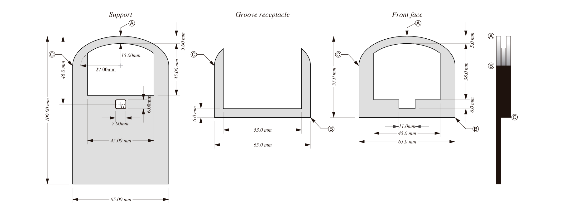
Ronchi-Tester Diagram
The Ronchi tester is designed to support commercial 2 in Ronchi rulings. Upper frame in the drawings (locate reference point A) is thought to serve as a structural support if your Ronchi ruling is not square shaped.
Chose acrylic plate 3 mm thick to build your Ronchi tester. This material is soft enough to be cut by using any kind of manual saw. Black acrylic avoids internal propagation of light in the material.
Square piranha super-flux LED is thought to be installed in the perforation H in the support section in the drawings. This kind of light source should have a circular internal emitter to avoid diffraction effects in a bi- Ronchigram. Generally, white light piranha super-flux LEDs show the described characteristic in the emitter.
A regular circular shaped LED can be installed if user changes the square H into a circle of the appropriate diameter.
Either piranha super-flux LEDs or regular circular shaped LEDs show a convex surface in the front. It is strongly advised to polish the front of the LED until reaching a flat surface. This action will make the LED to exhibit an approximately spherical wavefront emission. Be careful with the electrodes of the LED, you can use a magnifying glass for better viewing when polishing.
You should install the LED so that the front flat surface allows the Ronchi ruling slipping through the groove receptacle.
It is recommended that a piece of soft cloth is installed on the rear and front of the groove receptacle for keeping the Ronchi ruling free of scratches.
Consider, for ease, to use an old cellular phone battery charger as a power supply. Use Ohm law to select an appropriate resistance to limit the current in the LED. If you desire to control the brightness of the light source, consider selecting a fixed resistance which provides maximum brightness and add a variable resistance is series with the fixed one. For the most of the LEDs all the resistances values should be lower than 1 kΩ @ 1W dissipation power.
